York
08:00 AM - 05:00 PM
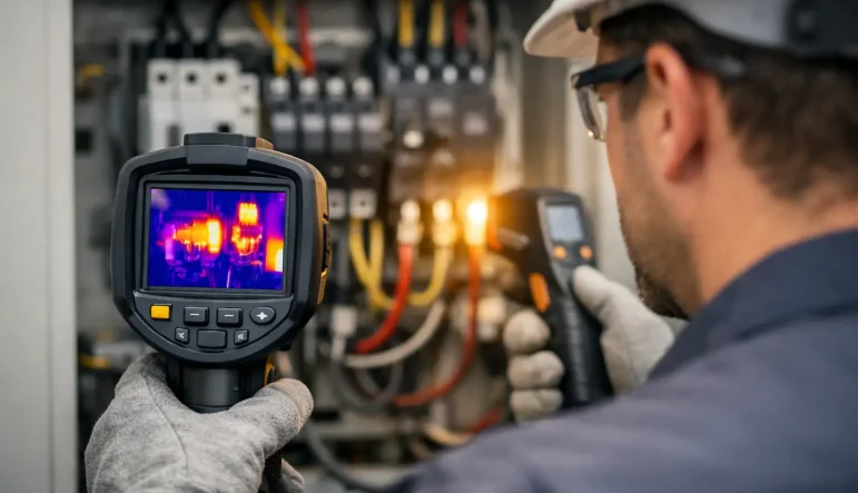
A distribution board can appear orderly, compliant and free from obvious damage while a loose termination is generating excessive heat behind a protective cover. This is where the question, what is thermography and can it be used in an electrical inspection?, becomes practical rather than theoretical. Thermal imaging gives a qualified electrical professional a way to identify abnormal heat patterns before they develop into equipment failure, unplanned downtime or fire risk.
For property managers, business owners, facilities teams and homeowners, thermography can add valuable evidence to an inspection strategy. It is not a substitute for electrical testing or sound engineering judgement, but it can reveal issues that conventional visual inspection alone may not show.
Thermography is the process of using a thermal imaging camera to detect and display infrared energy emitted from a surface. The camera converts differences in temperature into a visible image, often shown as a range of colours. Warmer areas may appear yellow, orange, red or white, depending on the camera settings and colour palette used.
In electrical work, unusually high temperatures can indicate that a component is under stress. Common causes include loose or deteriorating connections, overloaded circuits, unbalanced phases, corroded terminals, failing contactors, damaged cables and defective equipment. The thermal image allows the inspector to compare the temperature of similar components and investigate any significant variation.
The value is not simply in finding a hot item. Electrical equipment naturally warms under load, so the key is understanding whether the observed temperature is expected for that component, its duty and its operating environment. A competent survey considers the equipment rating, load conditions, ambient temperature, access, maintenance history and comparison with equivalent phases or circuits.
Yes. Thermography can be used as part of an electrical inspection, particularly where equipment is energised and operating under a meaningful load. It is widely useful in commercial premises, industrial facilities, transport infrastructure and larger residential installations with substantial electrical equipment.
A thermal survey is especially effective for inspecting distribution boards, switchgear, panel boards, motor control centres, busbars, isolators, cable terminations, transformers and connections associated with plant. In these locations, a developing fault may create heat long before there is a visible sign of deterioration or a protective device operates.
However, thermography does not replace the established elements of an electrical inspection. A full inspection may require visual assessment, dead testing, live testing where appropriate, verification of protective measures and documentation of the installation condition. Thermal imaging is best treated as an additional diagnostic tool that supports targeted maintenance and informed decision-making.
For example, an Electrical Installation Condition Report assesses the condition and safety of an installation against relevant requirements. A thermal scan may identify a hot connection that deserves immediate attention, but it cannot by itself confirm continuity, insulation resistance, polarity, earth fault loop impedance or the suitability of protective devices. Each method answers a different question.
Electrical resistance creates heat. A poor connection may have only a small increase in resistance, yet when current passes through it the heat generated can rise rapidly. A terminal that has loosened through vibration, thermal cycling or inadequate tightening can therefore become a localised hot spot.
Overloading has a similar effect. Cables, protective devices and switchgear are designed to operate within defined ratings and installation conditions. When a circuit is routinely carrying more current than anticipated, its temperature may increase across a wider area. Thermal imaging can help distinguish between a single hot termination and a circuit that is generally running too warm.
Three-phase systems provide another useful application. Under balanced loading, comparable phase components should normally show broadly similar thermal behaviour. If one phase is noticeably hotter than the others, this may point to load imbalance, a connection issue or a component fault. The finding still requires investigation, but it gives maintenance teams a clear reason to act before a fault becomes disruptive.
A useful thermographic inspection begins before the camera is switched on. The inspector should understand what equipment is being assessed, its normal operating duty, the likely load at the time of inspection and any known concerns. Surveying a lightly loaded board may not reveal a problem that only occurs during peak production, heating demand or building occupancy.
The equipment is then inspected from a safe position, with electrical safety controls suited to the task and the site. Where covers must be removed to view connections, the work must be planned carefully. Live electrical work carries risk and should only be undertaken when justified, controlled and completed by competent persons using suitable procedures and equipment.
Thermal images are normally supported by standard visual photographs, equipment identification and recorded observations. A report should state the location of each finding, the observed temperature pattern, the likely concern, the operating conditions and a recommended action. Clear reporting matters because a thermal image is evidence to be assessed, not a repair instruction in isolation.
At SJB Smart Electricals, this type of survey-led approach supports practical maintenance decisions across domestic, commercial and industrial environments. The objective is to give clients a clear understanding of condition, risk and the work needed to bring equipment back to a reliable standard.
Thermography has important limitations. Most significantly, it can only show temperature at the surface that the camera can see. A fault hidden behind insulation, an enclosure or another component may not be visible. A cool-looking item is not automatically fault-free.
The result also depends on the equipment being under load. A loose connection on a circuit that is currently switched off or drawing little current may show no meaningful heat rise. For this reason, surveys should be scheduled when systems are operating normally, or when representative load can be achieved safely.
Reflective surfaces can complicate interpretation. Polished metal, for instance, may reflect heat from nearby objects and create a misleading image. The material’s emissivity, the camera angle, the distance from the target and surrounding temperature all affect the reading. This is why an experienced operator does not rely on colour alone or treat one image as a final diagnosis.
Thermography also cannot establish every aspect of compliance. It will not prove that circuit labelling is correct, confirm test values, identify all hidden cable damage or replace periodic inspection requirements. It is a highly useful condition-monitoring method, but it remains one part of a proportionate inspection and maintenance programme.
The strongest case for thermal imaging is where electrical failure would carry a high operational or safety cost. In an office building, it can help facilities teams identify developing issues in main distribution equipment without unnecessary interruption. In an industrial setting, it can support planned maintenance for machinery and power systems where unplanned stoppage affects production.
It is also valuable in infrastructure environments, where electrical assets may serve critical operations and access windows are limited. A well-planned survey can focus maintenance resources on equipment showing signs of abnormal thermal performance, rather than relying only on fixed intervals or reacting after failure.
For homeowners, thermography may be appropriate where there are concerns about a consumer unit, persistent tripping, a warm accessory, high-load circuits or electrical equipment connected to heating, charging or outbuildings. The scale is smaller, but the principle remains the same: identify the cause, assess the risk and carry out the correct remedial work.
A hot spot should be investigated promptly, with urgency based on the severity of the temperature difference, the equipment involved and the consequences of failure. The remedy may be as straightforward as isolating the circuit and re-terminating a conductor to the correct specification. In other cases, the cause may be overload, damaged equipment, unsuitable design or a broader maintenance issue.
The right response is not always immediate replacement. Re-testing, load assessment and inspection of associated equipment may show whether the thermal anomaly was caused by a temporary operating condition or a persistent defect. Equally, where there is evidence of serious overheating, continued operation may not be appropriate.
Thermography is most effective when it forms part of an ongoing electrical maintenance plan. Repeated surveys create a useful baseline, making it easier to spot changing conditions and prioritise work before a minor defect becomes a costly interruption. The most helpful thermal image is not merely one that looks dramatic, but one that leads to a safer, properly evidenced decision.
Commercial electrician services for compliant, efficient premises, fro

Citroën has unveiled ë-Berlingo, the latest version of its multi-awa
